The load-bearing system of self controlled aircraft children’s amusement facilities is an important component of the facilities. What are the technical conditions and requirements for the load-bearing system of self controlled aircraft children’s amusement facilities? According to the new version of the national standard document “GB/T 20306-2017 Terminology for Amusement Facilities”, children’s amusement facilities are defined as “amusement facilities specifically designed for children’s play.” The definition of self controlled aircraft amusement facilities is “amusement facilities in which the passenger part is supported by a rigid support arm, rotates around a central vertical axis, and independently controls the lifting and movement in a similar form.” The new version of the national standard document “GB/T 18163-2020 General Technical Conditions for Self controlled Aircraft Amusement Facilities” states that “there are three common types of self controlled aircraft children’s amusement facilities, namely the self controlled aircraft series, octopus series, and other types of self controlled aircraft.
The new version of the national standard document GB/T 18163-2020 General Technical Conditions for Self Controlled Aircraft Amusement Facilities stipulates in Article 5 the following technical requirements for the load-bearing system of self controlled aircraft amusement facilities:
5.3.1 The frame of the passenger device should be made of metal material and have sufficient strength. The seat can be made of materials such as metal, wood, fiberglass, etc. The seat and the frame of the passenger device should be firmly fixed and easy to inspect and maintain.
5.3.2 Octopus series self controlled aircraft amusement facilities (excluding equipment with enclosed cabins and semi enclosed barrier door structures) and self controlled aircraft amusement facilities designed for acceleration in Zone 4 and Zone 5 according to GB 8408 regulations, only allow operators to manually or automatically release passenger restraint devices, and passengers are not allowed to open them on their own during operation.
5.3.3 The passenger device should be equipped with safety bars, safety gear bars, seat belts, handrails, and other safety devices that are suitable for the movement form, design acceleration zone, and passenger restrictions. The passenger restraint device shall comply with the provisions of GB 8408. For passenger devices without safety bars, seat belts, or safety barriers, it is advisable to install cabin doors or cabin barriers.
5.3.4 Self controlled aircraft amusement facilities with rolling motion should have quick reset measures. In the event of a power outage or emergency stop, it can restore passengers to their normal seating posture.
When there is a risk of the cabin being thrown out during operation due to the failure of a single component in the connection between the passenger device and the support arm of the loading system, effective safety measures should be taken.
5.3.6 The traction device that maintains the level of the passenger device should be equipped with safety measures. The connection between the traction device and the safety measures and the passenger device should be firm and reliable, and should not be directly fixed on the fiberglass.
When the power supply suddenly loses power or the equipment control system malfunctions, measures should be taken to safely lower the passenger device to the ground. ”
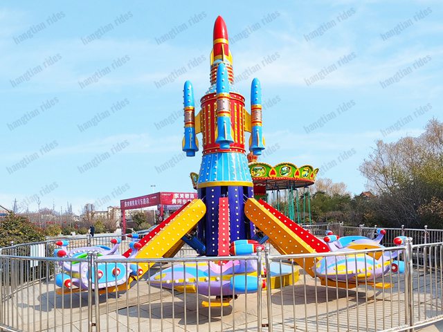
On site shooting of the self-control dinosaur case of children’s amusement equipment for aerospace amusement production, such as the self-control airplane
The new version of the national standard document “GB/T 18163-2020 General Technical Conditions for Self controlled Aircraft Amusement Facilities” stipulates in Article 6 that the inspection, testing, and testing requirements for the load-bearing system of self controlled aircraft amusement facilities are as follows:
6.3.1 Before and after the test, the passenger system should be inspected, including at least the inspection of the seat steel structure, safety bars and their locking devices, seat belts and their fixed connections.
6.3.2 Octopus series self controlled aircraft amusement facilities (excluding equipment with enclosed cabins and semi enclosed barrier door structures) and self controlled aircraft amusement facilities products designed for acceleration in Zone 4 and Zone 5 according to GB 8408 shall be inspected for passenger restraint devices using the test methods specified in the design. Passengers should not be able to open the passenger restraint device by themselves, and only operators are allowed to manually or automatically release the passenger restraint device.
6.3.3 Check passenger restraint devices, safety barriers, cabin doors or cabin barriers to ensure they meet design requirements.
6.3.4 The rapid reset function test of the passenger device should be conducted no less than 3 times for each operating condition allowed by the design, including no-load, off load, and full load conditions. The reset measures of the passenger device should meet the design requirements and be fast and effective.
6.3.5 The safety measures test for the connection between the passenger device and the support arm of the passenger system should be conducted according to the test method specified in the design, and the safety measures should be safe and effective.
6.3.6 The safety measures test of the traction device that maintains the level of the passenger device should be conducted according to the test method specified in the design. The connection between the traction device and the passenger device should be firm and reliable, and the safety measures should be safe and effective.
6.3.7 The manual opening test of the safety bar should follow the test method specified in the design, simulating that the safety bar can be manually opened when the automatic opening device fails. Each set of safety bars shall be tested no less than 3 times.
6.3.8 Safety bar locking device test: When the safety bar is closed and locked, a force of 500 N should be applied at the passenger armrest position, and the direction of the force should be perpendicular to the connecting line of the bar rotation force arm. The bar and its locking device should be effective and there should be no obvious deformation or damage. When there are two locking devices, test them according to the test method specified in the design to verify that each locking device should be able to function independently. Each type of locking device shall be tested no less than 3 times.
6.3.9 After the safety bar is tightened and locked, use a caliper to measure the displacement at the end, with no less than 3 measurement positions, and take the maximum value. The displacement at the end should be less than 35 mm.
The measures to safely lower the passenger device to the ground according to the test methods specified in the design shall be safe and effective in simulating sudden power outages or equipment control system failures