Drop Tower is a large outdoor amusement ride equipment, is an amusement ride themed around spinning and lifting, the cabin moves in a spiral ascent, descent, and continuous motion along the vertical column track, allowing passengers to experience thrills and joy during the lifting process! It is a very popular equipment in amusement parks.
Drop Tower as an upgraded version of large thrilling amusement equipment, in money-making capability has unexpectedly effective, its design and structure complex, operating height high, when riding not only can overlook the scenery, with the equipment’s spinning ascent and descent, brings visitors thrills and excitement, is incomparable.
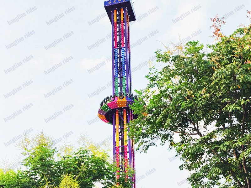
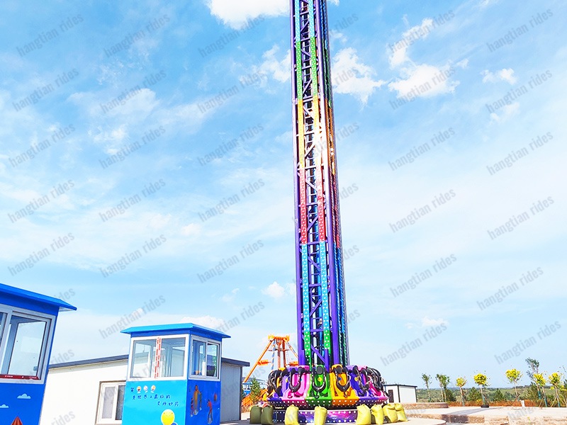
The total height is approximately 26 meters (including the lightning rod), with an operating height of approximately 19 meters. The top is equipped with a circular decorative element, and the tower body is fully clad in colored iron with installed lights. The disc-shaped cabin is fitted with 16 seats. Viewed as a whole, it resembles a towering iron pillar of color, with seats spiraling up and down, possessing significant visual appeal. Due to its spectacular exterior design, the equipment quickly became a bright and colorful attraction in major parks and amusement grounds after its launch.
Drop Tower is designed in accordance with 《Special Equipment Safety Supervision Regulations》、《Amusement Ride Safety Technical Supervision Regulations (Trial)》、《Amusement Ride Safety Code》(GB8408-2018)、《General Technical Conditions for Flight Tower Amusement Rides》(GB/T18161-2020) and other standards, meeting the requirements of relevant specifications. This ensures stable operation、low noise、comfortable riding、aesthetically pleasing appearance、reliable performance.
The concept is novel, the characteristics are distinct. Its main structure is a square high column, with 16 circular cabins arranged around it, the cabins are equipped with protective measures such as safety bars and seat belts. The entire operation system is equipped with sensors that detect the spiral climbing、descending speed of the cabins, monitoring the normal operation of the equipment. With colorful exterior decoration, interesting movement forms, visitors sit on the seats and gradually rise with the rotation of the turntable, as if soaring in the blue sky. Under the effect of centrifugal force, visitors swing and spin around the central column, like swallows circling and dancing in the clear sky, integrating entertainment、thrills and excitement into one, providing an endlessly enjoyable riding experience!
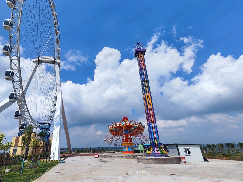
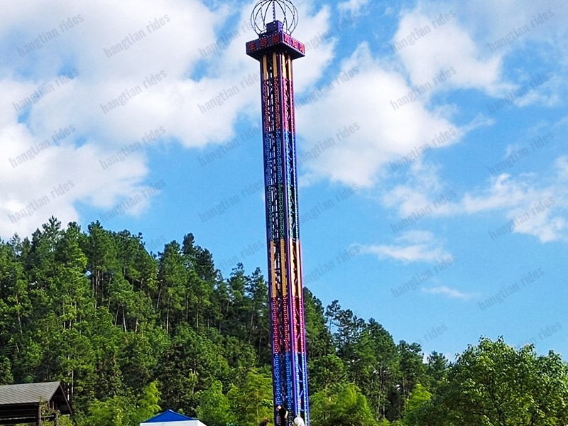
1.The overall design concept is novel, the structure is grand, the appearance is beautiful, the characteristics are distinct. The height overwhelms others, standing tall and upright, the tower body can be seen from afar overlooking the entire venue, regardless of appearance and momentum, among numerous equipment, it is particularly eye-catching, can be called an ideal iconic amusement equipment.
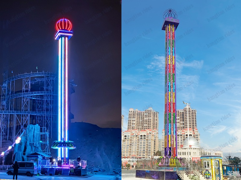
2.The tower body is entirely covered with colored iron and lights, brilliant and colorful, has a strong visual impact, customized lights are dazzling and cool, attracts tourists to flock to it;
3.For bystanders, it has great motivating force and attraction, the joyful laughter and exclamations of riders, easily arouse bystanders’ desire to participate and experience;
4.Adopts multiple protective measures such as pressure bars and safety belts, equipped with a sudden power failure slow descent protection system, safety factor is high;
5.Core components pump station uses high-standard configuration、oil cylinder uses customized enlarged models, own strength sufficient、load capacity large, performance more stable;
6.Footprint is small, only requires 9 meters*9 meters, this has an advantage among large equipment;
7.Single full load capacity 16 people, passenger capacity large, profitability considerable;
8.Design utilizes humanized advanced technology, enables the operating system to achieve simplification, one-key start, easy and convenient;
9.Strong fun、good experience effect, simultaneously accompanied by ascent descent and turntable’s own rotation, riding experience shocking and stimulating, passengesatisfaction very high;
10.Manufacturer is the association chairman unit enterprise, well-known brand, quality guaranteed;
11.The packaging and transportation work is all handled by the relevant team, value-added services worth anticipating;
12.The equipment installation and maintenance is meticulously operated by technical engineers, service thoughtful, after-sales worry-free;
13.After sale, the company will provide pre-job training for equipment operators, exclusive service, labor-saving and worry-free.
Using the hydraulic cylinder as the power source, the hydraulic cylinder moves downward, pulling the steel wire rope to drive the shuttle body upward, after reaching the vertex, it decelerates and stops, then, at the highest point, it relies on the potential energy generated by the cabin and human body gravity, slides down along the main body, performing repeated up-and-down motion; simultaneously, the shuttle body and main body rely on the reducer to drive the slewing bearing for rotational motion.
(1)Ambient temperature during use:0~40℃;
(2)Relative humidity during use:not more than 90%(When the maximum temperature is 40°C, the relative humidity shall not exceed 50%);
(3)Seismic intensity at installation site:≤8 degrees;
(4)Altitude at installation site:≤3000m;
(5)Operation shall be suspended when encountering:lightning, rain, snow, fog, frost, or main structure ice accumulation;
(6)Operation shall be suspended when wind speed exceeds 15m/s。
The equipment operation mode is set with two independent operation modes: manual mode and automatic mode. Manual mode can be used during equipment debugging, emergency rescue, and fault troubleshooting; daily passenger operation is strictly prohibited. Automatic mode is the daily passenger operation mode, achieved through PLC, and manual mode operation is strictly prohibited during daily passenger operation.
If an emergency occurs during operation, press the emergency stop button to cut off the equipment power supply, causing the equipment to stop immediately. Under power-off conditions, staff can manually operate the solenoid valves in sequence, allowing the shuttle body to automatically descend to the parking position. At this time, direct passengers to the safe area.
When equipment alarm or malfunction occurs, the alarm and fault information can be checked through the following aspects.
When PLC malfunction occurs, the LED indicator light on the PLC will provide an indication.
When equipment malfunction or alarm occurs, the fault indicator light or alarm indicator light on the operating console will also provide an indication.
1)Power phase loss, Solution: Check power wiring and rectify phase loss fault.
2)Lift motor switch connection wire detached, Solution: Reconnect the wire and close the switch.
3)AC contactor damaged, Solution: Repair or replace the contactor.
1)””Ready Button”” poor contact or damaged, Solution: Repair or replace;
2)””Control Power Switch”” poor contact or damaged, Solution: Repair or replace;
3)Wire detachment or poor contact, Solution: Reconnect properly;
1)Contactor failure, circuit breaker tripped, Solution: Reset
2)Operator misoperation, Solution: Turn off main power switch for 2 minutes then reset, switch to manual mode
3)PLC output contact damaged, Solution: Check and repair
1.Main structure shows no tilting.
2.Framework shows no rusting, no visible deformation.
3.Foundation shows no settlement.
4.All connections show no rusting, no visible deformation, welds show no cracks.
1.Ladder, maintenance platform and connection parts show no rusting or visible deformation.
2.Connection bolts show no loosening or detachment, welded parts show no cracks or damage.
1.The pressure bar weld seams show no obvious cracks or rust.
2.The pressure bar cylinder shows no air leakage, the air compressor indication is normal.
3.The connection points at the rear of the pressure bar show no damage, fractures, or visible crack
1.The safety belt shows no damage.
2.The buckle functions smoothly during opening and closing.
3.The fastening bolts show no loosening.
1.Anchoring bolts show no loosening or rust.
2.Pulley shafts show no cracks or visible deformation.
3.Pulley operation shows no jamming.
4.Connection parts show no visible deformation.
5.Wire rope grooves show no wear or eccentric wear.
6.Bearing lubrication is normal, showing no damage or abnormal wear.
1.Wire ropes show no slackness, the tension of each wire rope should be substantially consistent.
2.Wire ropes show no significant deformation or kinking.
3.Wire ropes should not have excessive oil stains; should not have broken strand phenomena, the number of broken wires should not exceed the standard, and there should be no excessive wear or internal corrosion. (Refer to Appendix 3 《Allowable Values for Wire Rope Broken Wires and Wear》)
4.The connections at the upper and lower attachment points for rope end fittings are securely fixed, fasteners show no loosening, and surfaces show no corrosion.
①To avoid equipment and personal accidents, all personnel involved in operation, maintenance, and installation of the equipment must be familiar with the structure and performance of this equipment.
②During equipment installation and dismantling, an isolation zone must be set up, and unauthorized personnel are not allowed to enter.
③During equipment operation, no stacking of any debris or entry of unauthorized personnel is allowed within the operating area to avoid affecting the operator’s work; lighting within the equipment operating area must be sufficient; during equipment operation, operators must not leave their work stations without authorization.
④During equipment maintenance, management operators should take away all keys from the operation console; press the emergency stop button; turn off all switches or the main switch and lock them; close entrances and exits to ensure that unauthorized visitors do not enter the equipment; during work at height, always wear safety helmets and safety belts; place a maintenance sign at a conspicuous position on the operation console.
(1)The main structure and shuttle body components, designed for outdoor working environments, are coated with primer and topcoat. Within a certain period, users should not only repaint all parts of the main structure but also routinely touch up primer and topcoat on any local areas where paint has peeled.
(2)After rain or snow, promptly remove accumulated snow and rainwater from the main structure, shuttle body, and seats.
(3)The equipment should be frequently cleaned, tidied, and wiped down to maintain cleanliness and aesthetic appearance.
(4)Bolted connections and pin connections between important components should undergo regular inspections; any potential hazards found must be promptly eliminated.
(5)If cracks are discovered on the surface of important welds, operation must be stopped immediately and appropriate measures taken promptly.
(6)Connection points (welds, bolts) of load-bearing metal structural components should be inspected annually. If weld cracks or loose nodes are found, repairs and tightening should be carried out promptly. Anti-corrosion maintenance for load-bearing metal structural components must be performed yearly. If rust, paint peeling, cracking, or weathering is observed, cleaning, derusting, and repair should be conducted.
(7)Daily, check the tightness at the following locations, ensuring fasteners are securely tightened as required: each pulley pin shaft location, each wire rope suspension fastening pin shaft location, the connection between the seat body and sliding parts, and the rollers.
(8)Perform external cleaning of the seats daily. Check fasteners for looseness, absence, or failure. Perform weekly maintenance on the pressure bar mechanism, cleaning the moving parts. The protective covers for the seats and pressure bar are made using polyurethane foam process. When cleaning, use a soft cloth soaked in water or detergent to wipe. Avoid contact with hard objects to prevent surface scratches and damage, which affects appearance. For FRP materials like the seat back covers, use a soft cloth soaked in water or detergent for cleaning. Avoid contact with hard objects to prevent surface scratches and damage, which affects appearance.
(9)Lubricate the bearings at the pulleys and rollers according to regulations, ensuring the rollers and pulleys rotate smoothly without jamming. When the wear on the shuttle body roller diameter reaches 4 mm (initial shuttle body roller diameter 160mm), or when the wear on the sliding roller diameter reaches 2 mm (initial movable pulley roller diameter 80mm), they should be replaced promptly.
(10)Wire Rope
① Inspect the wire rope for wear monthly, strictly adhering to the allowances for broken wires and wear specified in Table 18 of GB8408-2018 《Safety Code for Amusement Rides》 (see Appendix 3).
② Wire ropes require regular application of specialized wire rope lubricating oil, in principle once per month. If the wire rope remains sufficiently lubricated, the lubrication interval may be appropriately extended. If dryness is detected during routine inspections, lubrication should be performed promptly.
③ Every three months, perform a comprehensive cleaning of the wire rope surface. Use kerosene and a brush to carefully remove oil stains and dirt from the wire rope surface.
(11)After equipment adjustment is complete, use paint or an oil-based marker to mark inspection lines on the main structure. Specific requirements: Stop the shuttle body after rising 0.8-1 meters, and mark lines on both sides of the wire rope and at the connection between the shuttle body and main structure respectively (refer to the lock wire method).
During equipment operation, the tightness of the wire ropes on both sides of the shuttle body should be basically consistent. Inspection methods:
a. During trial operation, check the tilt of the shuttle body. Using one side as a reference, observe the other side. If the height difference of the marking line on the observed side exceeds ±10mm, adjust promptly.
b. Additionally, use a sensory method for auxiliary inspection: Position the shuttle body at the parking location, disconnect power, and pull the wire ropes on both sides sequentially to judge tightness based on the force required and the range of movement. If the difference is significant, adjust promptly. When adjusting, tighten or loosen the upper and lower nuts to achieve the vertical adjustment.
c. Apply Loctite threadlocker to the threaded connections at the upper and lower suspension points (except for the lower suspension point adjustment nuts).
d. Periodically check if the threaded connections at the upper and lower wire rope suspension points align with the lock marks. If loose, adjust promptly.
e. Periodically apply lubricating grease to the connection areas of the upper and lower suspension points to prevent rust.
(12)Other lubrication points should be lubricated regularly according to regulations.
◆ Inspection, upkeep, and maintenance of the mechanical system should be performed by professional maintenance personnel. Other unrelated personnel are not permitted to disassemble the equipment without authorization.
(1)When malfunctions occur in electrical equipment such as power and lighting systems, inspect and repair according to the electrical system schematic diagram.
(2)Before each rainy season, check the grounding resistance, which should not exceed 10Ω.
(3)Frequently inspect the connection between the lightning rod and the grounding wire.
(4)Check whether components, terminals, wires, and wire connections show signs of overheating, discoloration, odor, aging, looseness, detachment, damage, or insulation failure.
(5)Check whether abnormal vibrations or noises occur in the electrical components inside the control cabinet during operation; if any abnormalities are found, replace them promptly.
(6)Check whether the operating environment of the electrical system is suitable.
(7)Check whether protective circuits for phase loss and overload in the electrical system are functioning normally.
(8)Clean the interior of the control cabinet once a year to ensure it remains clean and dust-free.
(9)Check whether indicator lights and other display devices in the control cabinet are functioning normally.
(10)Check whether the motor operates normally; ensure the motor shows no adverse conditions such as overheating. Maintain the motor according to the instructions provided with the equipment.
(11)Keep the control room clean, tidy, and free of debris; ensure the control cabinet is clean and components are dust-free. When cleaning the control cabinet, use a soft cloth dampened with a neutral cleaner to gently wipe dirty areas or components. Do not use solvents, non-neutral cleaners, or alcohol-based solutions to wipe the control panel or components.
◆Inspection, maintenance, and servicing of the electrical system must be performed by qualified electrical maintenance personnel. Other unrelated personnel are not permitted to repair electrical equipment without authorization.
(1) The hydraulic system shall be used in an environment free from dust, strong radiation, and non-flammable or explosive conditions. The suitable temperature range for the system is 20°C – 55°C.
(2) After the system operating parameters are set, they shall not be altered arbitrarily, including system pressure, rotation speed, lifting speed, etc.
(3) System oil pipes, joints, and valve components: System pipelines shall be securely installed on channels, arms, and frames. After oil circulation, there shall be no vibration noise or oil leakage.
(4) Regularly inspect the performance of the hydraulic system and check for pipeline aging. Inspect pipeline connections, the junction between the piston rod and cylinder head, and the junction between the cylinder bottom and cylinder barrel for oil leakage. If any leakage is detected, immediately replace the seals at the leaking area. Periodically check and tighten screws, nuts, and joints at critical locations. Consistently maintain the external cleanliness of hydraulic cylinders, especially the piston rod surface. Regularly filter and replace hydraulic oil. Frequently check whether solenoid valves operate flexibly. Periodically inspect the connection terminals of solenoid valves.
(5) In the event of a sudden power failure during operation or other emergencies such as oil pipe rupture, implement manual control to lower the cylinder and safely bring the seats to the platform level for passenger evacuation.
(6) Requirements and methods for hydraulic oil usage:
a) Hydraulic oil cleanliness: Hydraulic oil, to be provided and filled by the user, must be filtered before injection. During operation, hydraulic oil cleanliness is ensured through forced filtration of the hydraulic system return oil, achieved by installing a high-flow low-pressure filter in the main return line of the hydraulic system. When the pressure difference across the filter exceeds the set value, clean or replace the filter element promptly.
b) Oil filling volume: The oil volume in the tank should be approximately 80% or more of the tank capacity.
c) Hydraulic oil operating temperature: The hydraulic oil operating temperature should be maintained within the range of 20°C – 55°C. When the oil temperature is below the specified value, run the oil pump idle for 10-20 minutes until the oil temperature reaches the specified range before operation. When the oil temperature exceeds the specified value, activate the cooling device.
For your and your family’s safety, and to ensure an enjoyable and pleasant ride, please adhere to the following guidelines:
First.:Consciously maintain public order, keep the environment clean, and do not bring food, beverages, or flammable materials onto the platform.
Second:Please enter in sequence with valid tickets and board or disembark according to staff instructions. During ride operation, no queuing visitors or other individuals may cross the barriers or enter areas posing potential hazards. Once the ride stops, passengers must exit immediately.
Third:Individuals with acrophobia, heart conditions, high/low blood pressure, cerebral thrombosis, neurological disorders, vertigo, severe myopia, pregnant women, those under the influence of alcohol, children under 1.2 meters in height, individuals weighing over 90kg, and persons over 65 years of age are not permitted to ride. (Including but not limited to the above conditions, visitors should consciously assess their physical suitability.)
Fourth:Before riding, securely store or remove loose items that may easily fall during high-speed motion (e.g., mobile phones, cameras, jewelry, watches, glasses, shoes, etc.) to prevent loss or items falling during operation. Do not bring pets, umbrellas, or any other objects that may pose risks to passengers.
Fifth:Passengers should follow instructions, take seats in order, secure the restraint bar and fasten the safety belt, and allow inspection by staff.
Sixth:Once the preparatory bell sounds and during operation, passengers must hold the restraint bar with both hands and refrain from playful interactions.
Seventh:Passengers should only unfasten the safety belt and release the safety bar after the ride has come to a complete stop, then exit in order via the designated exit.
Eighth:Please help maintain cleanliness and hygiene within the venue.
When the shuttle body stops in mid-air due to electrical or mechanical failure, switch the control button to manual mode and manually lower the shuttle body. After descending to the proper position, release the restraint bars and guide passengers to evacuate in sequence along the passageway. If any passenger experiences discomfort due to nervousness, they should be urgently transported to the nearest medical facility.
Note: This rescue plan is easy to implement, and the estimated time for complete passenger evacuation is 5-10 minutes.
When the shuttle body remains stationary in mid-air due to power failure or electrical malfunction rendering manual descent ineffective, completely disconnect all power sources and manually open the rescue valve at the base to gradually lower the shuttle body. After descent is completed, insert the emergency power supply into the socket at the seat base, release the restraint bars, and guide passengers to evacuate sequentially along the passageway. Should any passenger experience discomfort due to anxiety, provide immediate transport to the nearest medical facility.
Note: The estimated time for complete passenger evacuation using this rescue protocol is 10-15 minutes.
When the restraint bars still cannot be released after using the emergency power supply, pry open the piston rod of the locking cylinder for the restraint bars to manually release them.
Note: The estimated time for complete passenger evacuation using this rescue protocol is 5-10 minutes.